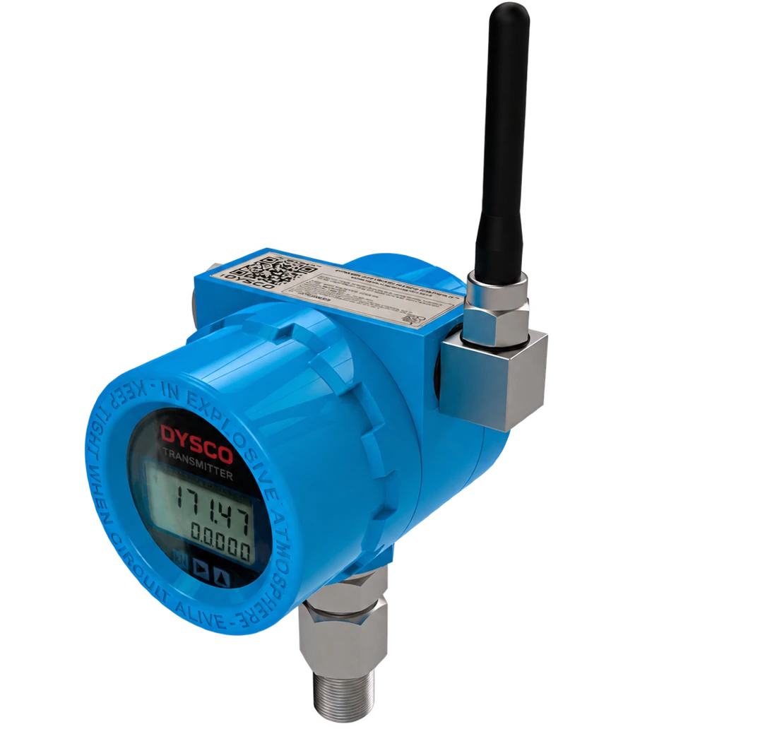
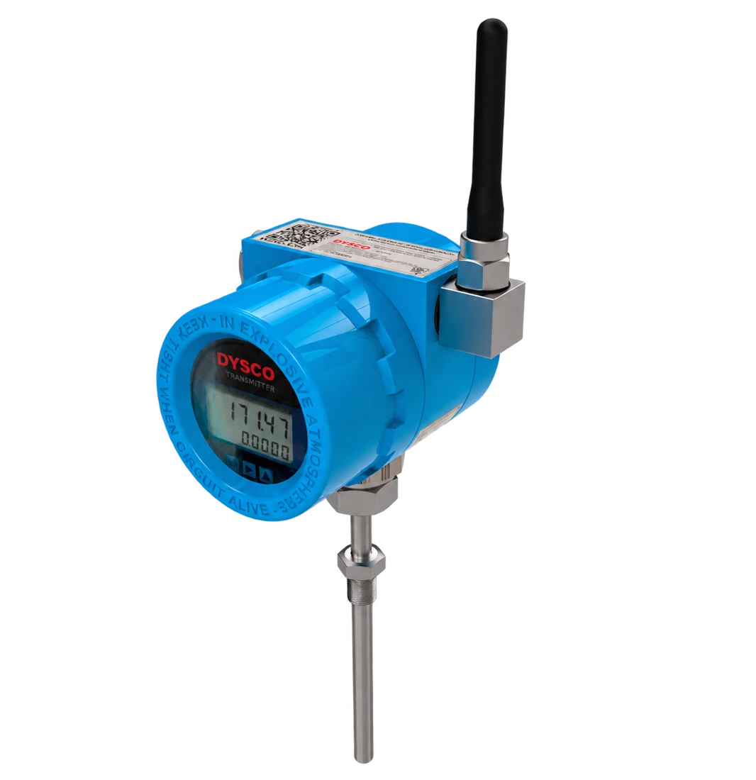
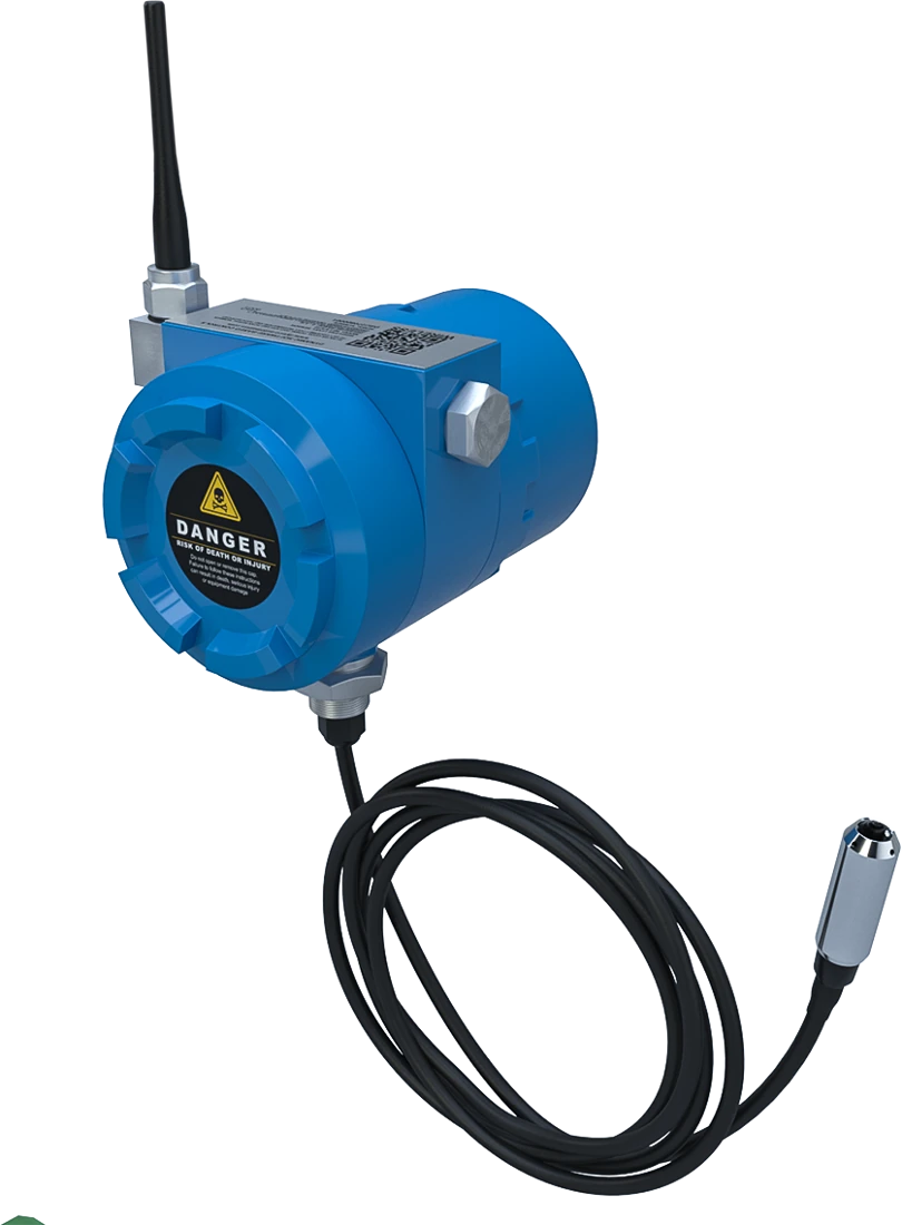
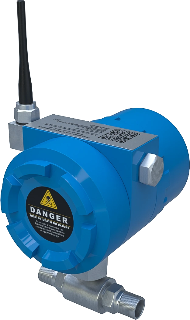
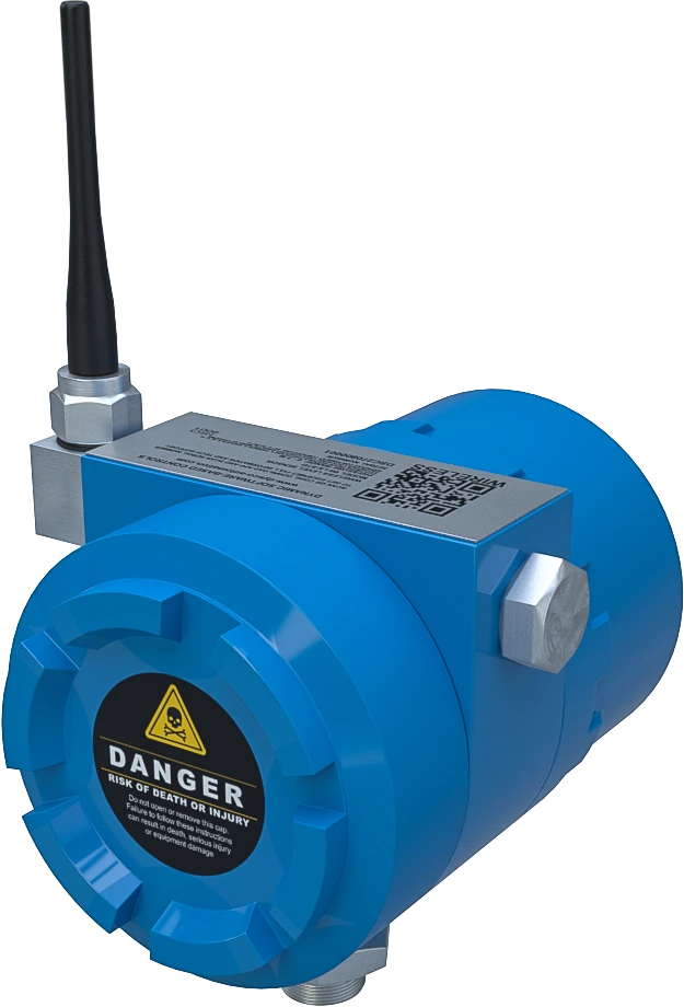
Piezoresistive pressure sensor with selectable ranges from −1 bar and 0…0.1 to 0…1,000 bar; 0.5 / 0.25 / 0.1% FS accuracy by configuration. LCD, radio up to 5 km and battery life up to 12 months with data sent every 3–5 minutes. Modbus through the WI-MG-STD gateway.
WI family: LCD, radio up to 5 km and Modbus through WI-MG-STD. Sensor/module battery life up to 12 months with data sent every 3–5 minutes; gateway externally powered.
WI family: LCD, radio up to 5 km and Modbus through WI-MG-STD. Sensor/module battery life up to 12 months with data sent every 3–5 minutes; gateway externally powered.
Measurement and configuration
Measurement principle
Piezoresistive; temperature compensation of zero and span
Selectable family ranges
From −1 bar and ranges from 0…0.1 to 0…1,000 bar; select nominal span
Configurable; battery-life reference with data sent every 3–5 minutes
Modulation / access
GFSK / CSMA/CA
Power, materials and mounting
Power supply
3.6 V battery; autonomy depends on sampling, transmission and battery
Operating temperature
−20 … +80 °C
Wetted parts
Stainless steel; verify fluid compatibility
Enclosure
Aluminum / IP67 according to configuration
Electrical entry
M20×1.5 or ½” NPT; IP68 direct cable on the applicable variant
WI-family common specifications
Family compatibility
Every WI device is compatible with the WI-MG-STD gateway
Modbus interface
RS-485 / Modbus RTU through WI-MG-STD; not a direct Modbus sensor output
Wireless coverage
Up to 5 km with line of sight and suitable link conditions
Design objective
Designed to meet Class I, Division 2; verify unit marking and installation conditions
Local indication
LCD
Battery life
Up to 12 months with data sent every 3–5 minutes, depending on battery and use conditions
Battery-life conditions
Battery-life reference: data sent every 3–5 minutes. Internal sampling is configured separately
ENGINEERING NOTES
Figures describe family options, not all available simultaneously. Confirm range, connection, materials, power and radio for the ordered unit.
Install depressurized and de-energized. Provide maintenance isolation; avoid severe vibration, flooding and strong electromagnetic sources.
The band and radio operation must match the variant and local installation regulations.
DIMENSIONS AND MOUNTING
Front 83 mm; width with radio 115 mm; depth 112 mm; Ø84 / Ø76 mm. Height to connection 132 mm, excluding antenna height. Drawing shows M20×1.5; final connection is selected.
Figures describe family options, not all available simultaneously. Confirm range, connection, materials, power and radio for the ordered unit.
CLOUDLOGGER SCADA INTEGRATION
Every WI sensor and module is compatible with WI-MG-STD. Sensor / I/O → wireless link → WI-MG-STD → RS-485 / Modbus RTU → PLC, RTU or cloudLOGGER SCADA. The gateway provides the family Modbus interface.
Modbus RTU is implemented on the gateway serial interface. Radio frequency and operation are verified for the installation country. If MQTT is required, it is provided at the integration layer, not claimed as a native sensor protocol.
Designed to meet Class I, Division 2. This design statement is not third-party certification; hazardous-area selection is verified against unit marking, documentation and installation conditions.
Which technical information applies to this equipment?+
The page distinguishes model-datasheet data from common platform references. Performance of the proposed variant is confirmed against its configuration and current documentation.
How should I interpret the drawing dimensions?+
Front 83 mm; width with radio 115 mm; depth 112 mm; Ø84 / Ø76 mm. Height to connection 132 mm, excluding antenna height. Drawing shows M20×1.5; final connection is selected. Figures describe family options, not all available simultaneously. Confirm range, connection, materials, power and radio for the ordered unit.
What should I confirm before equipment selection?+
Specify the variable or signal, operating conditions, connection, power, authorized band, distance and monitoring platform. Model-specific ranges and interfaces are defined for the selected equipment.
How does it integrate with cloudLOGGER SCADA?+
Every WI sensor and module is compatible with WI-MG-STD. Sensor / I/O → wireless link → WI-MG-STD → RS-485 / Modbus RTU → PLC, RTU or cloudLOGGER SCADA. The gateway provides the family Modbus interface.
Can I generate the technical datasheet from this page?+
Yes. The preview and PDF are built in your browser from the same technical data as this page. The PDF includes the image, specifications, dimensional drawing, integration and contact details.
What must be checked for hazardous-area installation?+
Designed to meet Class I, Division 2. This design statement is not third-party certification; hazardous-area selection is verified against unit marking, documentation and installation conditions.