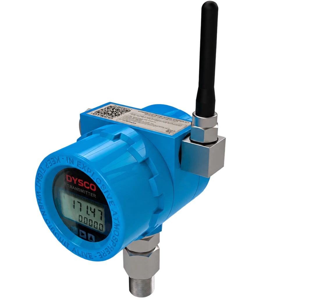
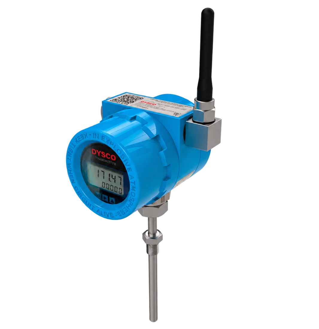
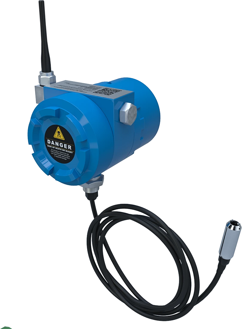
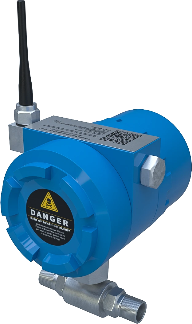
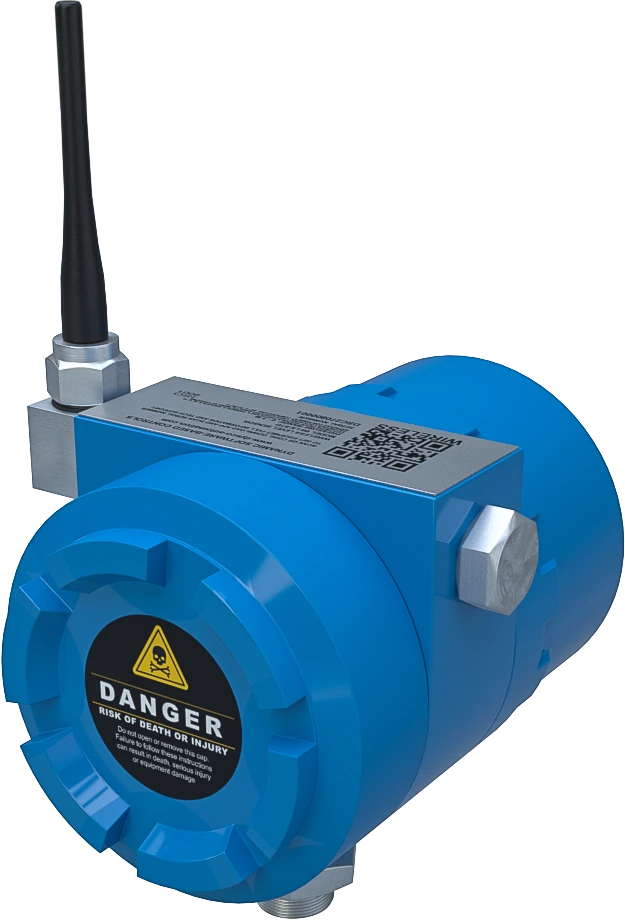
Gateway compatible with every WI-family sensor, wireless link up to 5 km and RS-485 / Modbus RTU output. Acquisition of 32 / 64 / 96 nodes by configuration, Float32 data and 10–28 VDC supply. Module 140 × 80 × 40 mm, excluding antenna.
Acquisition and Modbus gateway for the entire WI family; external 10–28 VDC supply.
Interfaces and Modbus data
Data interface
RS-485
Protocol
Modbus RTU
Serial format
8N1
Documented baud rate
Factory 115,200 bit/s; configurable 19,200 bit/s
Capacity by variant
32 / 64 / 96 sensors
Data format
32-bit IEEE 754 float; 2 registers per parameter; byte order 1234
Data per sensor
2 parameters / 4 registers / 8 bytes
Read and configuration
Function 03: read. Function 06: single-register write
CH0 map start
0x0009…0x000C; CHn starts at 9 + 4n (protocol address)
Radio and communications
Network
WSN
RF frequency
430–434.79 MHz
Frequency points
8 selectable, according to configuration
Antenna
Internal / external according to variant
Power, materials and mounting
Power supply
10–28 VDC
Operating temperature
−20 … +80 °C
Mounting
35 mm DIN rail
Dimensions without antenna
140 × 80 × 40 mm (height × width × depth)
WI-family common specifications
Family compatibility
Every WI device is compatible with the WI-MG-STD gateway
Modbus interface
RS-485 / Modbus RTU
Wireless coverage
Up to 5 km with line of sight and suitable link conditions
Design objective
Designed to meet Class I, Division 2; verify unit marking and installation conditions
ENGINEERING NOTES
Verify driver map and offset before integration. CH0 starts at protocol address 9; one-based drivers may display 10.
In diagnostic mode the first parameter changes to signal strength. Return to normal mode before using it as process data.
The band and radio operation must match the variant and local installation regulations.
DIMENSIONS AND MOUNTING
140 × 80 × 40 mm (height × width × depth), excluding antenna, as shown in the WI-MG-STD drawing.
Verify driver map and offset before integration. CH0 starts at protocol address 9; one-based drivers may display 10.
CLOUDLOGGER SCADA INTEGRATION
Every WI sensor and module is compatible with WI-MG-STD. Sensor / I/O → wireless link → WI-MG-STD → RS-485 / Modbus RTU → PLC, RTU or cloudLOGGER SCADA. The gateway provides the family Modbus interface.
Modbus RTU is implemented on the gateway serial interface. Radio frequency and operation are verified for the installation country. If MQTT is required, it is provided at the integration layer, not claimed as a native sensor protocol.
Designed to meet Class I, Division 2. This design statement is not third-party certification; hazardous-area selection is verified against unit marking, documentation and installation conditions.
Which technical information applies to this equipment?+
The page distinguishes model-datasheet data from common platform references. Performance of the proposed variant is confirmed against its configuration and current documentation.
How should I interpret the drawing dimensions?+
140 × 80 × 40 mm (height × width × depth), excluding antenna, as shown in the WI-MG-STD drawing. Verify driver map and offset before integration. CH0 starts at protocol address 9; one-based drivers may display 10.
What should I confirm before equipment selection?+
Specify the variable or signal, operating conditions, connection, power, authorized band, distance and monitoring platform. Model-specific ranges and interfaces are defined for the selected equipment.
How does it integrate with cloudLOGGER SCADA?+
Every WI sensor and module is compatible with WI-MG-STD. Sensor / I/O → wireless link → WI-MG-STD → RS-485 / Modbus RTU → PLC, RTU or cloudLOGGER SCADA. The gateway provides the family Modbus interface.
Can I generate the technical datasheet from this page?+
Yes. The preview and PDF are built in your browser from the same technical data as this page. The PDF includes the image, specifications, dimensional drawing, integration and contact details.
What must be checked for hazardous-area installation?+
Designed to meet Class I, Division 2. This design statement is not third-party certification; hazardous-area selection is verified against unit marking, documentation and installation conditions.